
Building Regulations Drawings: Full Plans Checklist for UK Homeowners
Building regulations drawings are the technical, construction-ready plans you must submit to prove your project complies with UK Building Regulations. For most extensions, loft conversions, and structural alterations, that means a Full Plans application. A complete package typically includes a site plan, existing and proposed floor plans, cross-sections showing construction build-ups, drainage layouts, structural references, and a compliance statement that references the relevant Approved Documents. Full Plans submissions take roughly 5–8 weeks for council review; a Building Notice allows work to start after 48 hours but offers no pre-checked compliance certainty.
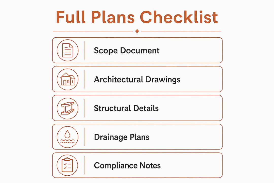
Minimum drawings and documents for a Full Plans submission:
- Location/site plan (typically 1:1250 or 1:2500 scale)
- Existing floor plans and elevations
- Proposed floor plans and elevations
- Cross-sections showing insulation build-ups and construction details
- Drainage layout (foul and surface water)
- Structural references or drawings (cross-referenced to engineer’s calculations)
- Window and door schedule
- Compliance statement referencing Parts A, B, L, and M where applicable
- Part L energy information (SAP or BRUKL for new builds and larger extensions)
- Ventilation and fire-safety notes where relevant
Timeline callout: Full Plans review usually takes a few weeks at most local authorities. A Building Notice lets you start shortly after notification but puts compliance risk entirely on the builder. For anything involving structural work, drainage changes, or loft conversion, Full Plans is the lower-risk route.
Table of Contents
- What are building regulations drawings, and how do they differ from planning drawings?
- What drawings and documents go into a Full Plans package?
- What technical detail do your drawings actually need to show?
- Full Plans vs Building Notice: which route should you choose?
- Why do building control applications get rejected, and how do you fix them?
- Who prepares each part of the drawings, and what does it cost?
- How do you package and submit your drawings correctly?
- How Clockfortress prepares a Full Plans package from start to finish
- Key Takeaways
- The part of this process most guides skip over
- Clockfortress handles your Full Plans submission from drawings to approval
- Official references and further reading
What are building regulations drawings, and how do they differ from planning drawings?
Planning drawings and building regulations drawings are not the same thing, and confusing them is one of the most common mistakes homeowners make. Planning drawings show what a building will look like and whether the proposed development is acceptable in land-use terms. Building regulations drawings show how it will be built to meet safety and performance standards. The two processes run separately, and you can have planning permission without building regulations approval, and vice versa.
A set of building regulations drawings is a construction-ready technical document. It must demonstrate compliance with the functional requirements set out in the Approved Documents. The most commonly referenced Parts for household projects are:
- Part A (Structure): load paths, beam sizes, padstones, foundations
- Part B (Fire safety): means of escape, fire separation, protected routes
- Part L (Conservation of fuel and power): insulation, U-values, airtightness
- Part M (Access): door widths, thresholds, accessible facilities
When is a Building Notice appropriate? For minor, low-risk work on a straightforward property where the builder is experienced and the scope is simple, a Building Notice can work. But it relies entirely on the inspector catching issues during site visits, with no pre-checked drawings to fall back on. Full Plans is preferred for most householder projects precisely because compliance is confirmed before a single brick is laid.
Pro Tip: Before you commission drawings, write a one-page scope document listing every element of the project: structural changes, drainage alterations, roof type, insulation strategy, and any access requirements. Hand it to your designer at the start. This single step prevents the most common cause of revision cycles: scope creep discovered mid-drawing.
What drawings and documents go into a Full Plans package?
A Full Plans submission under Regulation 14 of The Building Regulations 2010 must be accompanied by the required particulars. In practice, that means a coordinated set of drawings and supporting documents. Nothing should be left for the inspector to assume.
Core drawings checklist:
- Location plan at 1:1250 or 1:2500 showing the site in context, with the application site outlined in red
- Site plan at 1:200 or 1:500 showing the building footprint, boundaries, access, and drainage outfall points
- Existing floor plans at 1:50 or 1:100 for every affected level
- Proposed floor plans at the same scale, clearly distinguishing new from existing construction
- Existing and proposed elevations for all affected faces
- Cross-sections through the building showing floor-to-ceiling heights, roof pitch, insulation build-ups, and foundation depth
- Construction detail drawings at 1:5 or 1:10 for key junctions: wall-to-floor, eaves, window reveals, cavity closers, and damp-proof course positions
- Drainage layout showing foul and surface water runs, pipe sizes, falls, inspection chambers, and connection points
- Window and door schedule listing sizes, materials, glazing specifications, and U-values
- Roof build-up detail showing structure, insulation, ventilation, and weatherproofing layers
Supporting documents checklist:
- Structural calculations and structural drawings, cross-referenced to the architectural plans
- Part L energy information: SAP calculation for new dwellings; BRUKL output or equivalent for extensions and commercial work
- Ventilation strategy referencing Part F (extract rates, background ventilation, purge ventilation)
- Fire safety notes where Part B applies: escape windows, fire doors, smoke alarms, protected stairways
- Specification notes: materials, product performance data, U-values, fixings, and damp-proofing products
- Compliance statement referencing each relevant Approved Document and directing the reviewer to the supporting drawing or document
File grouping for a typical household extension (10–15 page pack):
A basic pack usually groups drawings into: architectural sheets (plans, elevations, sections, details), a drainage sheet, a structural sheet cross-referenced to the engineer’s separate calculation document, and a specification/compliance statement sheet. The compliance statement sits at the front and acts as the index, directing the plan-checker to the relevant sheet for each functional requirement.
What technical detail do your drawings actually need to show?
Building control officers are not looking for beautiful drawings. They are looking for specific, verifiable information that lets them confirm compliance without guesswork. The level of detail required is higher than most homeowners expect.
Scales, title blocks, and drawing conventions
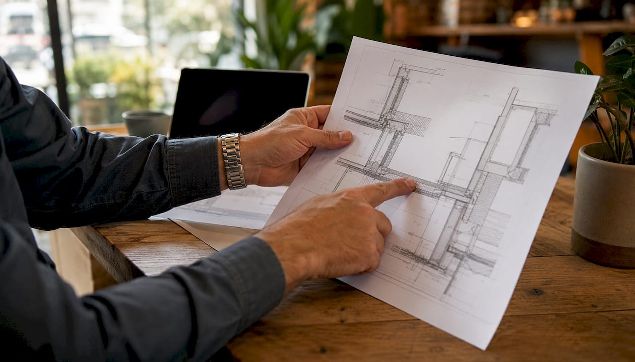
Plans and elevations should be drawn at 1:50 or 1:100. Detail sections showing construction build-ups must be at 1:5 or 1:10 so insulation layers, cavity widths, and fixings are legible. Every sheet needs a title block containing the project address, drawing title, drawing number, revision number and date, scale, and the name of the person who prepared it. A north point is mandatory on the site plan. Scale bars are preferable to written scales alone, because a printed drawing may be reproduced at a different size.
Part L and thermal performance
Insulation build-ups and U-values must appear either on the section drawings or in the specification notes, and they must be traceable to the compliance statement. For a typical cavity wall extension, that means stating the wall build-up layer by layer (outer leaf, cavity, insulation type and thickness, inner leaf, plasterboard) and the resulting U-value. The target U-values under Part L for extensions are set in the Approved Document; your drawings need to show you have met or bettered them. For new dwellings, a SAP calculation is required. For commercial schemes, a BRUKL output is the standard. Clockfortress prepares Non-Domestic Part L and BRUKL energy statements as part of its compliance drawing service.
Key construction details
The details that most often cause plan-check queries are junctions: where insulation meets structure, where the damp-proof course meets the cavity closer, where a steel beam bears on a padstone. Each of these needs a named detail drawing at 1:5 or 1:10. The structural member locations shown on the architectural plans must carry a cross-reference bubble pointing to the engineer’s calculation reference. If the engineer specifies a 203×133 UB at a particular span, that beam designation should appear on the architectural drawing at that location, not just in a separate structural document the plan-checker has to hunt for.
Pro Tip: Add a simple cross-reference table to your cover sheet: one column for the compliance topic (e.g., “Part A - Structure”), one for the relevant drawing number, and one for the supporting document reference (e.g., “Structural Calcs Rev A, Sheet 3”). This single page can eliminate half the queries a plan-checker would otherwise raise.
Full Plans vs Building Notice: which route should you choose?
The decision between Full Plans and Building Notice comes down to one question: how much compliance risk are you willing to carry onto the site?
Full Plans is the right choice for:
- Any project involving structural alterations (steel beams, load-bearing wall removal, new foundations)
- Loft conversions and basement conversions where Part B fire safety applies
- Extensions where drainage connections are being altered
- Any project where the client wants certainty before committing to a builder’s contract
Building Notice may be appropriate for:
- Simple, non-structural internal alterations by an experienced contractor
- Like-for-like replacements where no new compliance territory is entered
- Projects where speed of start is more important than pre-checked certainty
The official GOV.UK guidance is clear: Full Plans gives you a checked and approved set of drawings before work starts, removing the risk of discovering a compliance problem mid-build. The council’s plan-checking period runs 5–8 weeks. A Building Notice allows work to start after 48 hours, but any compliance issue found during inspection must be corrected on site, often at significant cost.
Private Approved Inspectors offer an alternative to local authority plan-checking. Their lead times can be shorter, and some offer a more consultative approach during the design stage. They issue a Final Certificate on completion rather than a local authority Completion Certificate, but both are equally valid for mortgage and conveyancing purposes.
After approval: what happens next
- Approval notice issued (or Approved Inspector’s Initial Notice accepted)
- Site commencement notification to building control (usually 48 hours before starting)
- Staged inspections: foundations, damp-proof course, structural frame, drainage, insulation, and final
- Any design changes during construction must be re-submitted as amendments before being built
- Completion Certificate (or Final Certificate from an Approved Inspector) issued after satisfactory final inspection
Why do building control applications get rejected, and how do you fix them?
Most plan-check queries are predictable. The same issues appear repeatedly, and almost all of them come down to missing information rather than genuinely non-compliant design.
Common fail points and their fixes:
- Missing structural cross-references. Fix: add a cross-reference bubble on every structural element in the architectural plans, pointing to the engineer’s calculation sheet and reference number.
- Inadequate junction details. Fix: draw every critical junction at 1:5 or 1:10. Wall-to-floor, eaves, window reveals, and cavity closers are the ones most often queried.
- Vague thermal notes. Fix: state the full build-up layer by layer with product names, thicknesses, and the resulting U-value. “Insulation to meet Part L” is not sufficient.
- Unclear drainage connections. Fix: show pipe sizes, falls (e.g., 1:40 for 100mm foul drain), inspection chamber positions, and the point of connection to the public sewer or soakaway.
- Insufficient fire and escape detail for conversions. Fix: show escape window sizes and cill heights, fire door positions and ratings, smoke alarm locations, and any protected stairway construction.
Vague specifications create a second problem beyond the plan-check: they create ambiguity on site. When a drawing says “insulate to current standards” without specifying a product or thickness, every builder will price it differently, and the cheapest interpretation usually wins. That scope ambiguity turns into a variation order when the inspector arrives.
Pro Tip: Include a short compliance summary on your cover sheet listing each Approved Document Part that applies to the project, the specific functional requirement, and the drawing or document that demonstrates compliance. Plan-checkers work through a mental checklist; give them yours first.
Who prepares each part of the drawings, and what does it cost?
A Full Plans pack is rarely produced by a single person. Different elements require different expertise, and understanding who does what helps you assemble the right team and avoid gaps.

| Drawing / Document | Typical Preparer | Notes |
|---|---|---|
| Site plan and location plan | Architect, architectural technologist, or CAD drafter | Often sourced from OS mapping; must be accurate to site boundaries |
| Existing and proposed floor plans | Architect or architectural technologist | Requires measured survey of existing building |
| Elevations and sections | Architect or architectural technologist | Sections must show construction build-ups |
| Construction detail drawings | Architect or architectural technologist | Junction details are the most time-intensive element |
| Structural drawings and calculations | Structural engineer | Charged separately; essential for any structural work |
| Part L / SAP / BRUKL | Energy assessor or specialist consultant | Required for new dwellings and larger extensions |
| Drainage layout | Architect, technologist, or drainage engineer | May require input from the local water authority |
| Compliance statement | Architect or technologist | Ties the whole pack together |
Typical cost ranges for household projects: Drawing fees for a standard single-storey extension typically range from £800–£2,500 or more, depending on complexity and who you commission. Structural calculations are usually charged separately by the engineer. Council application fees vary by project size and are set by the local authority. Budget for both drawing fees and council fees as separate line items.
Production timelines: Simple household packs can be turned around in days for straightforward projects. A loft conversion with structural coordination typically takes 7–10 working days for the drawing package, plus the engineer’s turnaround for calculations. Complex new builds require several weeks and more intensive coordination between the architect, structural engineer, and energy assessor.
Pro Tip: When commissioning a drawing package, ask specifically whether the fee includes: submission to building control, responding to plan-check queries, and issuing revised drawings if amendments are required. Many quoted fees cover production only. A scope that includes submission support and one round of query responses is worth paying more for.
How do you package and submit your drawings correctly?
Getting the drawings right is half the job. Packaging and submitting them so the plan-checker can navigate them quickly is the other half. Regulators increasingly expect a digitally maintained “golden thread” of information: clearly indexed, labeled drawings linked to a compliance statement.
| Element | Requirement |
|---|---|
| File format | PDF (vector, not scanned image) for all drawings and documents |
| Drawing sheets | One PDF per discipline group, or one multi-sheet PDF with bookmarks |
| Structural calculations | Separate PDF, clearly titled and cross-referenced to drawing numbers |
| Naming convention | Project address, drawing number, revision, date |
| Title block | Present on every sheet: address, drawing number, revision, scale, preparer |
| Scale bar | Included on every scaled drawing |
| North point | On site plan and all floor plans |
| Drawing index | Listed on cover sheet or as a separate index document |
Version control matters. Every revision should carry a revision letter (Rev A, Rev B) and a date. When you submit amendments after approval, the revised sheets must be clearly marked with a revision cloud or bubble around the changed area, and the revision block in the title block must record what changed and when. This is how the golden thread between the approved drawings and the actual construction is maintained. Any material change on site that was not shown on the approved drawings should be re-submitted before being built.
Pre-submission checklist:
- Title block complete on every sheet
- Scale bar present on every scaled drawing
- North point on site plan
- Drawing index on cover sheet
- Compliance statement references each drawing by number
- Structural calculations cross-referenced to architectural drawing numbers
- Revision numbers and dates current
- File names follow a consistent convention
How Clockfortress prepares a Full Plans package from start to finish
Clockfortress (trading as Fortress Associates) follows a structured process from initial brief to completion certificate support. Here is how a standard house extension Full Plans pack is produced.
Step-by-step process:
- Brief and scope review. The project scope is confirmed in writing: structural changes, drainage alterations, insulation strategy, access requirements, and any Part B fire-safety triggers.
- Site survey. Measured survey of the existing building to establish accurate baseline drawings.
- Drawing production. Architectural plans, elevations, sections, and construction detail drawings produced to the required scales and conventions.
- Structural engineer coordination. Structural drawings and calculations commissioned and cross-referenced to the architectural set.
- Part L input. Energy performance information prepared: U-value calculations, SAP or BRUKL output where required, and ventilation strategy.
- Compliance statement. A compliance statement is prepared referencing each Approved Document Part and directing the reviewer to the relevant drawing or document.
- Submission. The complete package is submitted to the local authority or Approved Inspector, with a drawing index on the cover sheet.
- Plan-check query management. Any queries raised by the plan-checker are addressed promptly, with revised drawings issued where needed.
- Inspection support. Clockfortress coordinates with the building control officer at key inspection stages to close any site queries quickly.
What the client receives:
- Full set of architectural drawings (PDF, vector format)
- Structural drawings cross-referenced to engineer’s calculations
- Part L / energy compliance documentation
- Drainage layout drawing
- Compliance statement and drawing index
- Submission confirmation and query correspondence
Clockfortress’s amend-or-refund guarantee means that if a submitted report or drawing package is rejected, it will be amended at no additional cost, or a refund is issued. Every package is validated against current standards before submission, using live official data with no hidden costs.
Key Takeaways
A compliant Full Plans submission requires a coordinated set of technical drawings, supporting documents, and a compliance statement that references the relevant Approved Documents - submitted as clearly indexed, version-controlled PDFs to your local authority or Approved Inspector.
| Point | Details |
|---|---|
| Full Plans is the lower-risk route | Council review takes several weeks but confirms compliance before any work starts on site. |
| Minimum pack contents | Site plan, existing/proposed plans, sections, drainage layout, structural references, and a compliance statement referencing Parts A, B, L, and M. |
| Technical detail matters | Every junction, U-value, and structural cross-reference must appear on the drawings - vague notes are the leading cause of plan-check queries. |
| File organization is part of compliance | Use consistent naming, revision numbers, and a cover-sheet index so plan-checkers can navigate the pack without raising avoidable queries. |
| Clockfortress delivers the full pack | Fortress Associates prepares the complete Full Plans package, coordinates structural and Part L inputs, and backs every submission with an amend-or-refund guarantee. |
The part of this process most guides skip over
Most articles about building regulations drawings focus on what to include. The harder question is why so many packs still fail plan-checking even when they contain the right drawings.
The answer is almost always coordination, not content. The architectural drawings show one thing, the structural calculations assume something slightly different, and the compliance statement references a drawing number that does not exist in the submitted set. None of these are catastrophic errors individually, but together they create a cascade of queries that can add four to six weeks to a programme.
The fix is not more drawings. It is a single person or team holding the whole pack together: checking that beam references on the architectural plans match the engineer’s calculation references, that the U-values on the section drawings match the SAP output, and that the compliance statement index points to real, submitted documents. That coordination role is often undervalued when homeowners are comparing quotes, because it is invisible in the final product. You only notice it when it is missing.
There is also a tendency to treat the compliance statement as an afterthought, something written after the drawings are done. The better approach is to draft the compliance statement first, as a checklist of what the drawings must prove, and then produce the drawings to answer it. That reversal changes the quality of the whole pack.
Clockfortress handles your Full Plans submission from drawings to approval
Preparing a Full Plans pack that passes first-time plan-checking requires more than good drawings. It requires coordinated structural cross-references, accurate Part L inputs, a properly indexed compliance statement, and someone who knows how to respond to plan-check queries without losing weeks on avoidable back-and-forth.

Clockfortress (Fortress Associates) prepares the complete Full Plans drawing package for UK homeowners, self-builders, and small developers. The service covers architectural drawings, drainage layouts, construction details, structural coordination, Part L energy compliance, and the compliance statement, all submitted as a coordinated, indexed pack. Fixed-fee pricing with no advance payment means you review the completed documents before paying. Every submission is backed by the amend-or-refund guarantee: if building control raises a rejection, Clockfortress amends the drawings at no extra cost, or issues a refund. Get your Full Plans pack started at clockfortress.com/building-regulations.
Official references and further reading
The sources below are the authoritative references for UK building regulations compliance. When preparing a compliance statement, cite these directly.
Primary legislation and official guidance:
- The Building Regulations 2010, Regulation 14: the statutory basis for Full Plans submissions, including the required particulars and additional copies where Part B applies.
- GOV.UK: Preparing information for a building control approval application: official guidance on what to include in a submission, how to structure the compliance statement, and how to reference drawings.
Approved Documents (available from GOV.UK):
- Approved Document A (Structure): load-bearing elements, foundations, and structural stability.
- Approved Document B (Fire safety): means of escape, fire separation, and protected routes.
- Approved Document L (Conservation of fuel and power): U-values, SAP, BRUKL, and airtightness.
- Approved Document M (Access to and use of buildings): door widths, thresholds, and accessible facilities.
For local authority plan-check times and Approved Inspector contacts:
Contact your local authority’s building control department directly for current plan-check turnaround times, as these vary by council and workload. The Procore UK construction drawings guide provides a useful overview of drawing types and the golden thread concept for digital submissions.
“Construction documents shall be of sufficient clarity to indicate the location, nature and extent of the work proposed and show in detail that it will conform to the provisions of the applicable regulations.” This principle, common to building control frameworks across jurisdictions, captures exactly what UK building control officers expect from a Full Plans submission: not artistic impression, but verifiable technical evidence.
For free tools to help with pre-submission site checks, including flood zone lookups and planning constraint reviews, Clockfortress offers a free UK planning tools hub covering flood zones, air quality management areas, daylight, carbon, and biodiversity net gain.
Recommended
- Building Regulations Drawings - Full Plans Submission UK | Fortress Associates
- 21 Free UK Planning Tools - Constraints, Flood, Fees, Daylight | Fortress Associates
- Free UK Planning Tools: Flood Zone, AQMA, Daylight, Carbon, BNG - Fortress Associates
- Do I Need Planning Permission for an Extension? Free PD Checker - Fortress Associates
Need help with a UK planning project?
Fixed-fee daylight & sunlight reports and Building Regulations drawings - plus flood risk assessments, air quality assessments, energy statements and sustainability statements for planning applications across the UK.
Request a free quote